Mechatronics
PCB Design
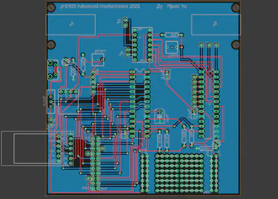
The above picture is a PCB (printed circuit board). It is designed by Eagle which is a 2D CAD software. The purpose of this PCB is to build a small mobile robot. In the Eagle software, I make a library for all items and then create a schematic (below). Then I draw the layout for the actual wires. Finally, I generate the gerber files and send them to the boarding house which can manufacture the PCB.
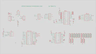
The above picture is a schematic diagram for the PCB. I connect a PIC32 microchip, a regulator, a USB connector, a slide switch, some LEDs, some resistors, some capacitors, some pushbuttons, an IO expander, an IPS Display, an h-bridge breakout, and a camera by using the PCB.
Microcontrollers
IMU (Inertial Measurement Unit)
This is a demonstration for the IMU (inertial measurement unit), which is a sensor used to calculate position, velocity, and acceleration. The chip shown in the video is LSM6DS33. I create some C language scripts and connect the circuit to control the IMU through PIC32. In this video, when I tilt the board, the bar in the display will be longer in the direction of tilt. After I push the button, the IMU will display the value of temperature, velocity, acceleration, and FPS.
Clock
The above video is a demonstration of a stopwatch which is built by PIC32 and an LED board. After I push the button, the stopwatch will start to count seconds. When I push the button again, the stopwatch will stop and show the value of seconds.
LED (Light-emitting diode)
This video shows four LEDs that shines the rainbow. The name of these LEDs is WS2812B. They are also controlled by PIC32. I change the PWM value and set some timers to set the color of these LEDs.